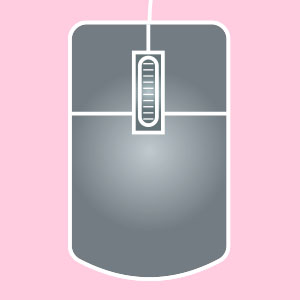
A computer mouse with a left, middle, and right button. Three-button mice may also have a middle wheel that can click and scroll. Use the left and right buttons to left-click and right-click.
3D
Having (or appearing to have) three dimensions: width, height and depth.
3D Modeling
The process of creating a 3D representation of an object, for instance using specialized computer software.
3D Printing
The process of turning a digital 3D CAD model on your computer into a solid, 3D object in the real world using a specialized 3D printer.
A
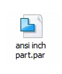
ANSI Inch
A template option that lets you design and measure in the Imperial System (inches).
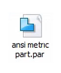
ANSI Metric
A template option that lets you design and measure in the Metric System (millimeters).
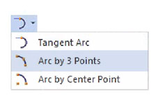
Arc by 3 Points Tool
A tool that creates an arc connecting 3 specified points.
B
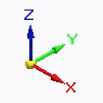
Base (Base Coordinate System)
Symbol in the center of the working area that lets you see the X, Y and Z axes of the design.
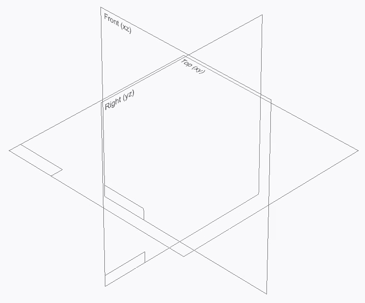
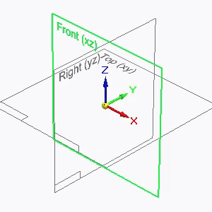
Base Reference Planes
The three reference planes at the center of the Solid Edge workspace. The planes intersect at right angles and define the views: Top (XY), Right (YZ), and Front (XZ).
Brainstorming
Spontaneous ideation alone or in a group.
C
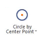
Circle by Center Point Tool
A tool that draws a circle based on a specified center and radius.
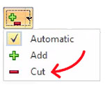
Cut Tool
A tool with a scissors icon that removes an object and copies it to the clipboard.
D
Delete
Lets you remove objects or features. Can be accessed by right-clicking and selecting from the drop-down menu, or in the mini-toolbar near the top of the screen. Or hit function + delete on the keyboard.
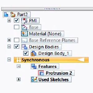
Design Bodies
A menu under Pathfinder that lists all the self-contained 3D parts of a model.
Design Body
A self-contained 3D part of a model. A model can be made up of one or more bodies.
Diameter
The width of a circle through its center.
E
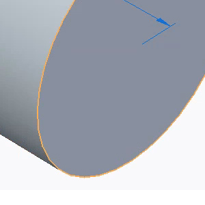
Edge
The line where two faces of a 3D shape meet.
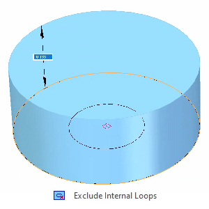
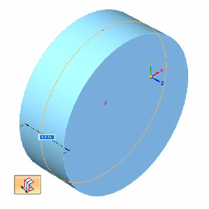
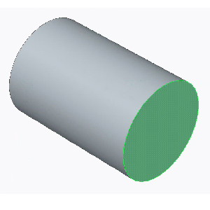
Extrude – Exclude Internal Loops
With Exclude Internal Loops selected, two concentric circles will extrude as a solid cylinder. The inner circle (the “internal loop”) is ignored.
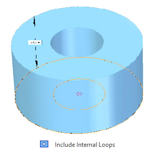
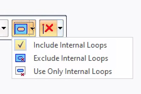
Extrude – Include Internal Loops
With Include Internal Loops selected, two concentric circles will extrude as a hollow tube. The inner circle (the “internal loop”) is factored in.
Extrude – Internal Loops
An option that determines whether or not your design will be affected by other lines or sketches touching or on top of the face you’re extruding.
Extrude – Symmetry
An option that extends a sketch symmetrically, in opposite directions from the sketch you select. Tap SHIFT to turn symmetry on/off while using the Extrude tool.
Extrude Tool
A tool that extends a sketch through space to either add or remove material from your model.
F
Face
A flat or curved surface that makes up the outside of a 3D shape. For example, a cube has 6 faces; a cylinder has 3.
I
Ideation
The process of coming up with ideas.
Iteration
The process of repetition and modification that leads to new ideas and improvements.
L
Line Tool
A tool that creates a line between two points.
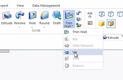
Lip Tool
A tool that creates a lip or groove along an edge. You can choose whether material is added to form a lip, or removed to form a groove.
M
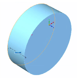
Model
An object represented in 3D.
O
Offset Tool
A tool that duplicates and shifts a sketch to a specified side and distance.
P
PAR
A template option that lets you design an object in parts.
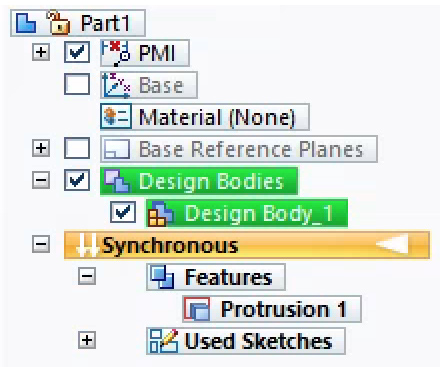
Pathfinder
Solid Edge menu that lets you turn on/off Base Reference Planes, the Base Coordinate Symbol, Design Bodies, and PMI (measurements). Located in the top left corner in Solid Edge.
Perpendicular
When two objects are oriented 90 degrees apart so they appear to intersect at a right angle.
Plane
A flat surface typically used for drawing 2D sketches in 3D space. In theory, the size of a plane is infinite, but it’s displayed on screen at a fixed size to make it easier to select and visualize.
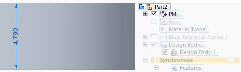
PMI
Stands for Product Manufacturing Information and lists out the measurements used in a design.
Prototype
A test design that helps determine if the design works or needs to be modified.
R
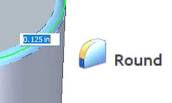
Round Tool
A tool that rounds selected edges of an object by a specified amount.
S
Select Tool
A basic cursor tool that allows you to highlight or deselect elements.
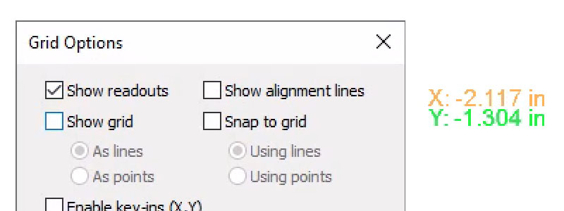
Show Readouts
A setting under Grid Options that displays in numerals where your cursor is within the coordinate system.
Sketch
A 2D drawing.
Sketch profile
The 2D outline of a sketch.
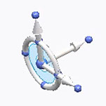
Steering wheel
Lets you rotate and move objects in three different ways: rotationally, linearly, or with freeform movements.
STL
“Standard Triangle Language” or “Standard Tessellation Language” — a file format that’s widely used for CAD and 3D printing.
Subtract
A setting of the Extrude tool that removes material from existing 3D bodies. Also called “Cut”.
T
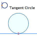
Tangent Circle Tool
A tool that creates a circle that touches an existing sketch or surface at only one point, without intersecting it.
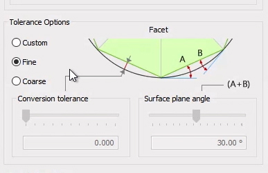
Tolerance
Every 3D printer has a specific tolerance, meaning the prints it makes might deviate slightly from the actual CAD design dimensions by a particular amount.
Trim Tool
A tool that removes unwanted parts or portions from your design sketch.
U
Undo
Undo the previous action using the back arrow icon, or keyboard combination control + Z.
Upcycle
Taking an object, especially one that cannot be reused or recycled, and adding value to it by giving it a new purpose.
V
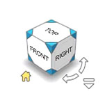
Viewcube
Solid Edge icon that lets you control the orientation of the object you’re designing, so you can view it from a particular side. For example: top, bottom, left, right. Located in the bottom right corner in Solid Edge.