Module 3
Things That Go
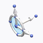
Project: Water Bottle Car
After sporting events, assemblies, outdoor picnics or other gatherings you often see them lying around uselessly…empty plastic water bottles. Hold one up. Turn it on its side. What if that empty bottle became the body of a toy car?
Let’s get things moving!
For this module, we’ll be upcycling a plastic water bottle and turning it into the design of your own car. Your innovative mindset along with 3D modeling will help you create the other parts you’ll need to make your car go – wheels, and axles that attach to the wheels and connect them to your car’s body (also known as the chassis.)
Explore how your design decisions affect how far and fast you can get your car to move. Try making your wheels larger, thinner, thicker, etc. and see what happens!
You will need:
- A plastic bottle
- 2 rubber bands
- 4 bottle caps or other round objects for “wheels”
- Two wooden skewers or other thin dowels for “axles”
- Hot glue


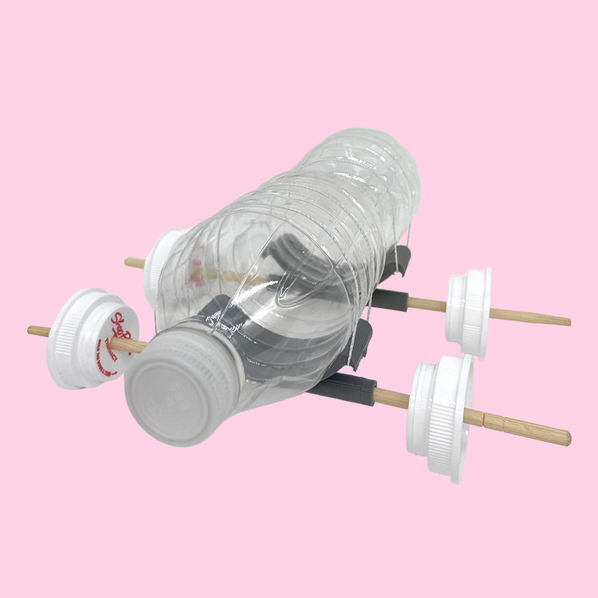
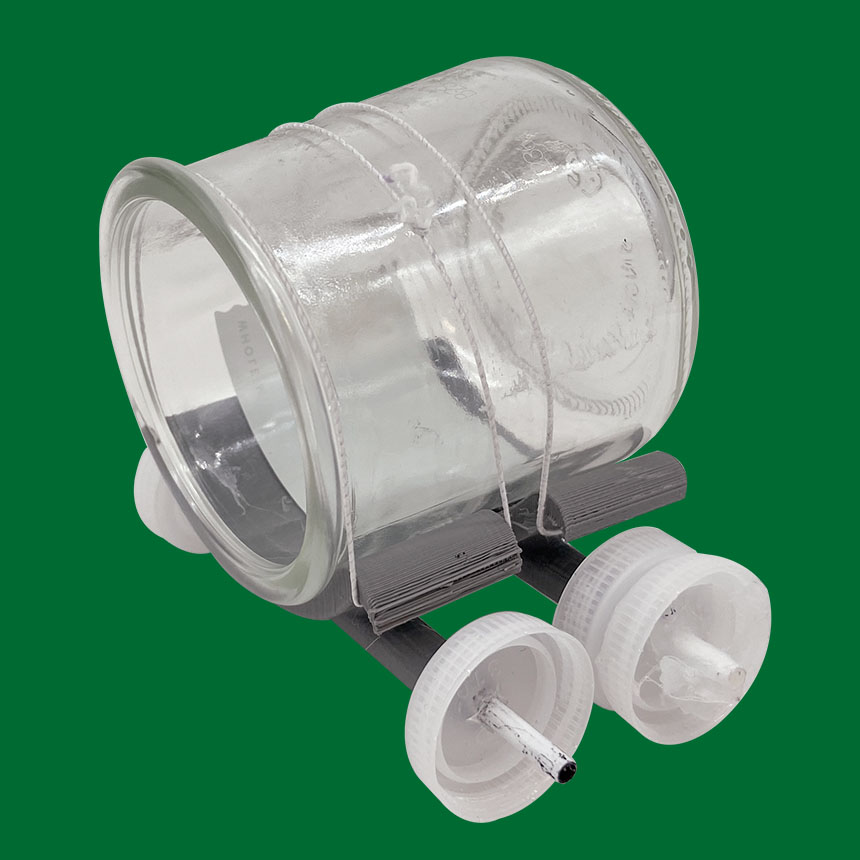
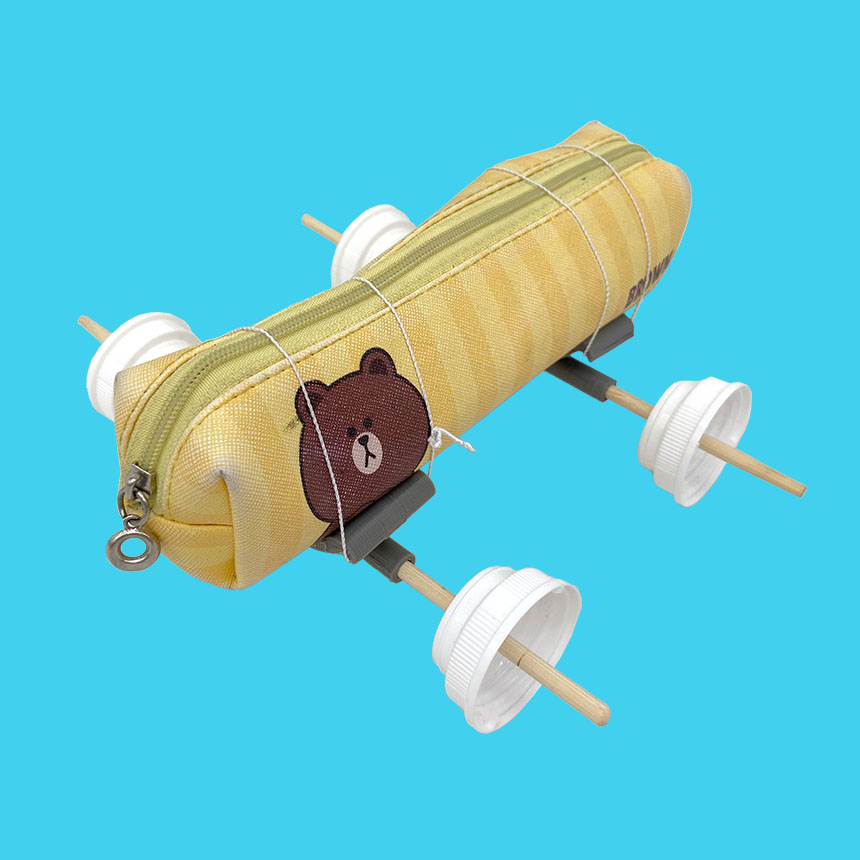
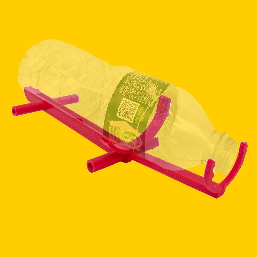
Before you can make your car move, you need a way to attach axles and wheels to the bottle. You’ll begin by creating a piece that will connect to the axles. This 3D printed part of your car’s body, (or chassis) will sit under the bottle with a hook on either side. String a rubber band from one hook to the other to attach the bottle to it.
Let’s get started!
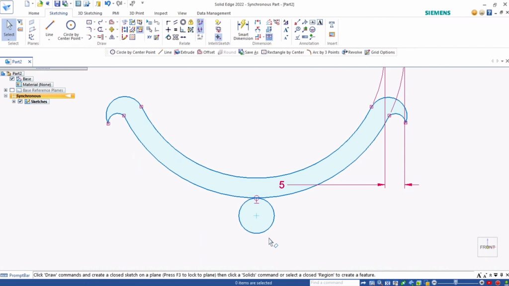
To begin, measure the Diameter of your water bottle. Using a Poland Springs bottle, we found that it measured 65 mm across. If you use a different kind of bottle, take your own measurements and use those throughout.
Tip: We will be printing two pieces to attach the axles to the chassis—one for the front of the car, and one for the back. Depending on the shape of your bottle, you may have different diameters where the front and rear axles go. In that case, repeat these steps for the front and back separately.
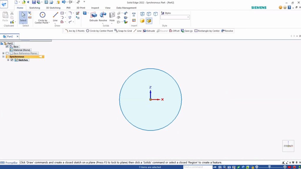
- Open a new ANSI Metric part document.
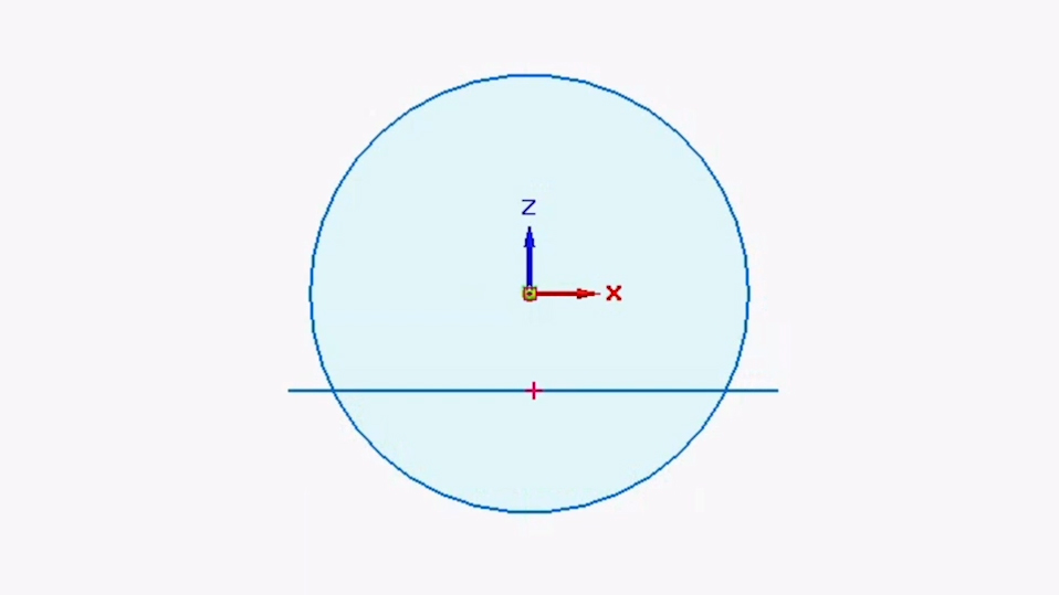
- Select the Circle by Center Point Tool. Start by sketching a circle as a visual representation of your water bottle as seen from the top or bottom ends. This reference will ensure that the printed chassis fits your bottle exactly.
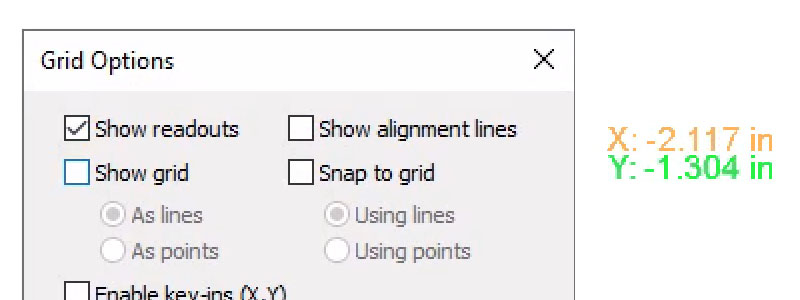
- Under Sketching tab, Draw section, click the Grid Options button in the bottom right and enable Show Readouts. This will show the coordinates where we are placing points and help you match our measurements.
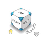
- Select the Front View of the Viewcube.
- Using Show Readouts, locate the point 0, 0. Click to place the center point of your circle there.
- Type 65 mm for the diameter of your bottle (or your own measurement, if it’s different from ours) and hit Enter.
Next we’ll create the arc (or semi-circle) shape that will hold the round side of your bottle.
Under the Sketching tab, Draw section, select the Line Tool. This allows us to draw straight lines.
Draw a line across the bottom of the circle. Click to place the starting point and click again to place the end point. Press Escape to finish drawing.
Let’s remove the parts of the sketch we don’t need.
- Under Sketching, Draw, select the Trim Tool. Now if we click on a sketch outline, the Trim tool will remove it.
- Click the outline of the top part of the circle.
- Click on each segment of the horizontal line to remove it.
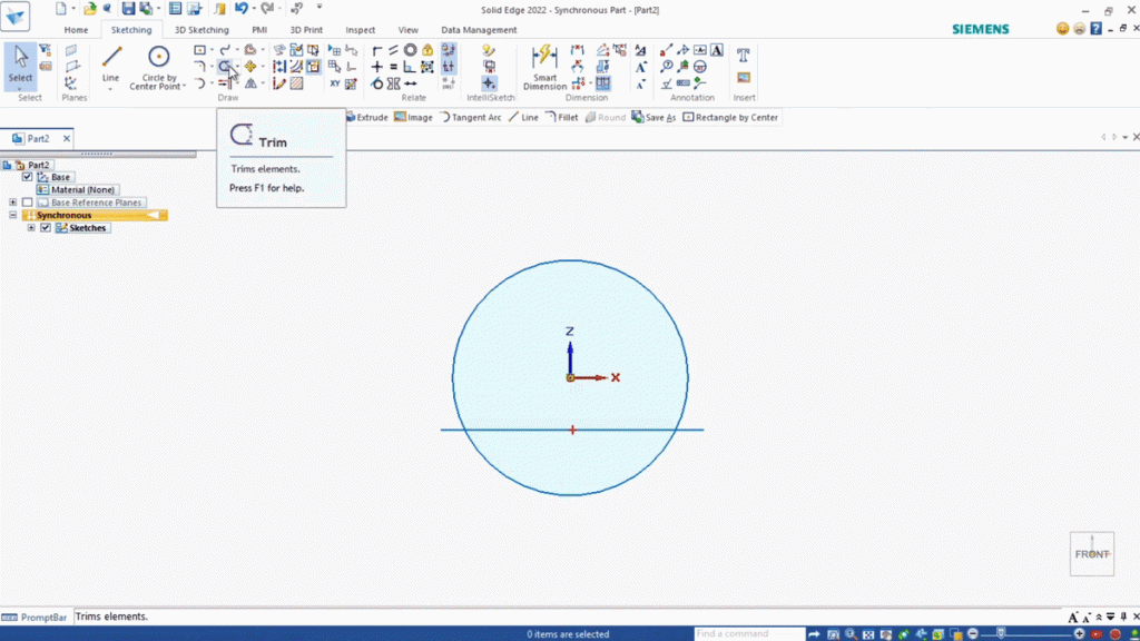
Now you should be left with the arc you created. Time to draw the bottom edge of the chassis.
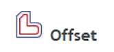
- Under Draw, select Offset Tool. This tool makes a copy of an existing line a set distance away from the original.
- Select the arc sketch you created.
- Type 5 mm for the distance.
- Hit Enter or click the green checkmark in the mini-toolbar to apply the distance.
- Using your mouse, move your cursor so that the offset sketch appears below your original arc sketch and left-click to confirm the placement. Now you should have two matching arcs 5 mm apart.
- Hit Escape to stop using the tool.
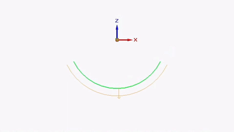
For this next part, you’re going to connect the end points of the two lines and create a hook that a rubber band can grip onto. The rubber band will hold the chassis to the bottle.
Tip: You don’t have to use the exact measurements we’re using—just make sure the final shape is similar so it can hold a rubber band.
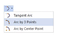
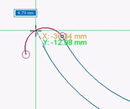
- Select the Arc by 3 Points Tool.
- Select the left endpoint of the top arc sketch to plot your first point.
- Move the mouse left and down, past the endpoint of the bottom arc sketch. A dotted line should appear:
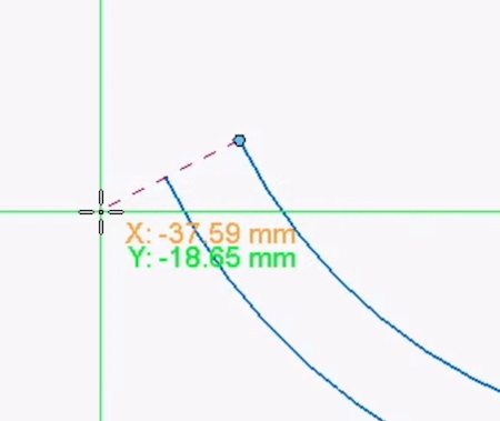
- Click to place the second point as shown.
- For the final third point of your arc, move your mouse and left-click so that the arc curves upward, similar to the image below.
We’ll use these same steps to complete the hook. Once again using the Arc by 3 Points tool, connect the end of your newly created arc with the endpoint of what will become your bottom arc.
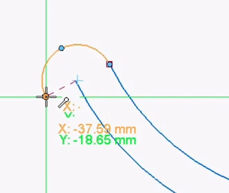
For the final, third point of that second arc, drag your mouse upwards and click to form a hook shape similar to the image below.
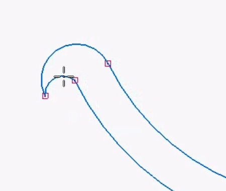
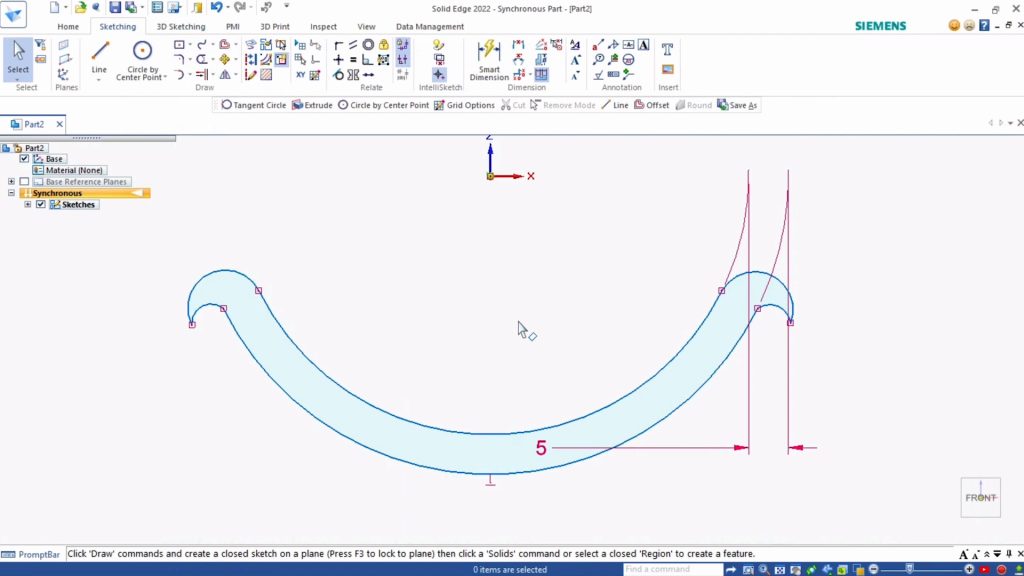
Repeat the above steps with the right side of the chassis design. You should end up with a design similar to below:
Now you’re going to create a hollow tube that will hold the rotating axle shaft.
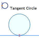
Under Draw, Circle by Center, select Tangent Circle Tool. This tool lets you draw a circle starting at a set point. You’ll use it to place the tube directly under the arced bottom of the chassis.
- At the bottom midpoint of your drawing, click to plot the first point of your circle.
- Mouse down and type 9 mm for the diameter of your circle.
- Hit Enter to lock in the measurements.
- Left-click to place the circle. (Reference the screenshot below.)
- Hit Escape to exit the tool.
Tip: Depending on what you use for the axle, you may want to increase the diameter of the tube you make.
For the next step, you’re going to rotate the circle by 90 degrees so that your finished tube will extend left to right under the arc of the chassis.
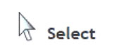
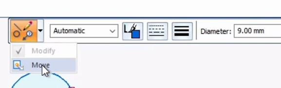
- With the Select Tool, click the outline of the circle sketch you just created.
- A mini-toolbar should appear near the top of your workspace.
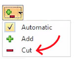
- In the mini-toolbar, select the drop-down arrow next to the orange button and change it to Move.
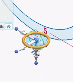
- After selecting Move, a Steering wheel symbol will appear over the circle, looking something like this. (It doesn’t matter if the arrow is pointing up rather than down.)
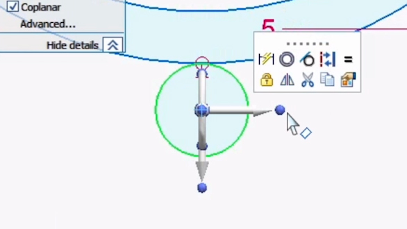
The ring of the steering wheel can be used to rotate the circle. However, right now the ring is oriented top to bottom, and you need it to rotate left to right instead. Let’s adjust it:
- Hold the Shift key and click the blue ball at the end of the arrow pointing to the side. The option to enter an angle measurement should appear.
- Enter 90 degrees and hit Enter. Click anywhere on the screen to confirm the measurement.
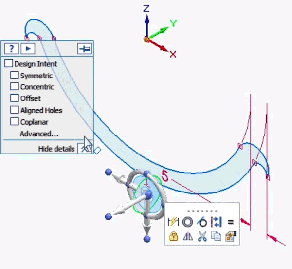
- Now your steering wheel should be rotated into the correct position:
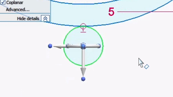
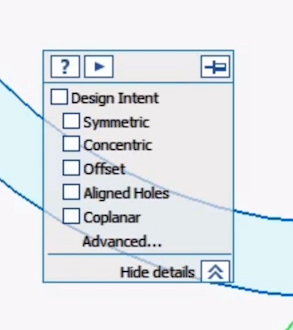
- Look for a mini pop-up with a checklist titled Design Intent and make sure everything is deselected. This way the rotation only affects your circle, and not the chassis arc as well.
- Switch to the Home View using the Viewcube.
- Hover over the ring-like part of your steering wheel so that it highlights orange.
- Click on the ring. The option to enter an angle measurement should appear.
- Enter 90 degrees to rotate your circle to be Perpendicular to the chassis arc.
- Hit Enter.
- In the mini toolbar, select Move again.
- This time click the white up/down arrow to move the circle up so it overlaps with the chassis arc slightly.
- Click to place the circle in the new location.
To complete your tube, you’ll add a second inner circle.
- Using the Viewcube, switch to the Right View.
- Select the Circle by Center Point Tool. Using the previous circle you sketched, plot a new circle with the same center point as the first one.
- Enter 6 mm for the diameter measurement. This will fit an axle with a 5 mm diameter. Hit Enter to confirm.
- Hit Escape.
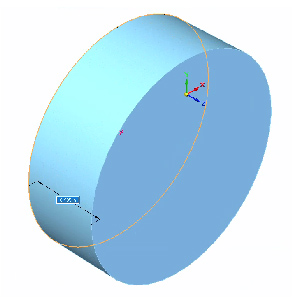
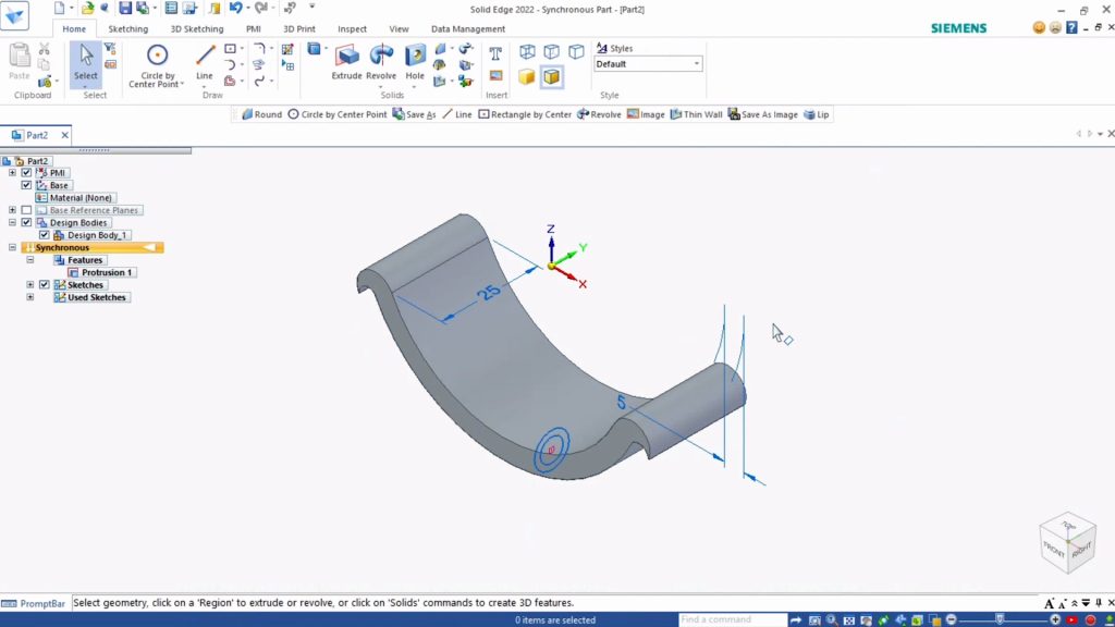
Now let’s add three-dimensionality to the two 2D sketches you’ve created. The arc of the chassis will go first:
- Switch to Home View.
- Under Home tab, Solids select the Extrude Tool.
- Have the Face selection on, and Extrude - Symmetry on.
- Click on the face of the hooked arc.
- Hit Enter and extrude by 25 mm. Hit Enter again to confirm.
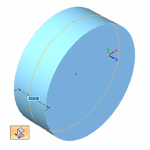
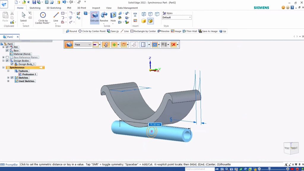
Next you’ll extrude the tube beneath the chassis:
- Select the Extrude Tool.
- Click on the outlines of the highlighted area:
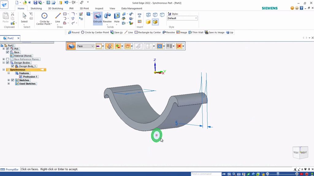
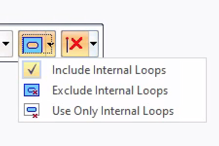
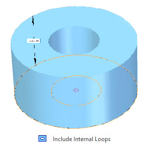
- In the mini-toolbar that appears, make sure that Face, Extrude - Symmetry and Add is on. This way your tube will extrude symmetrically to the left and right of your chassis. Also make sure Extrude - Internal Loops is set to Extrude - Include Internal Loops, so that your tube will include a hollow in the middle.
- Hit Enter.
- Use 75 mm for the extrude measurement and hit Enter to confirm.
You designed both chassis and axle holder as one piece. But we want to be extra sure that the water bottle holder is firmly attached to the part that will hold the axles. Let’s add some material around the spot where the two parts connect to strengthen it.
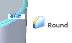
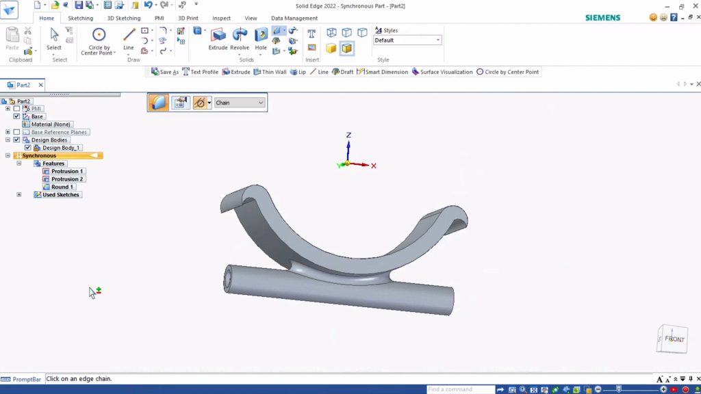
- Select the Round Tool.
- Using your keyboard commands, zoom in and rotate your view of the axle holder. Focus on the place where the chassis arc meets with the axle holder.
- With the Round tool selected, hover over the section of the design where the two pieces meet. It’s is a small area where they touch, and it should highlight orange to indicate that you are right over it:
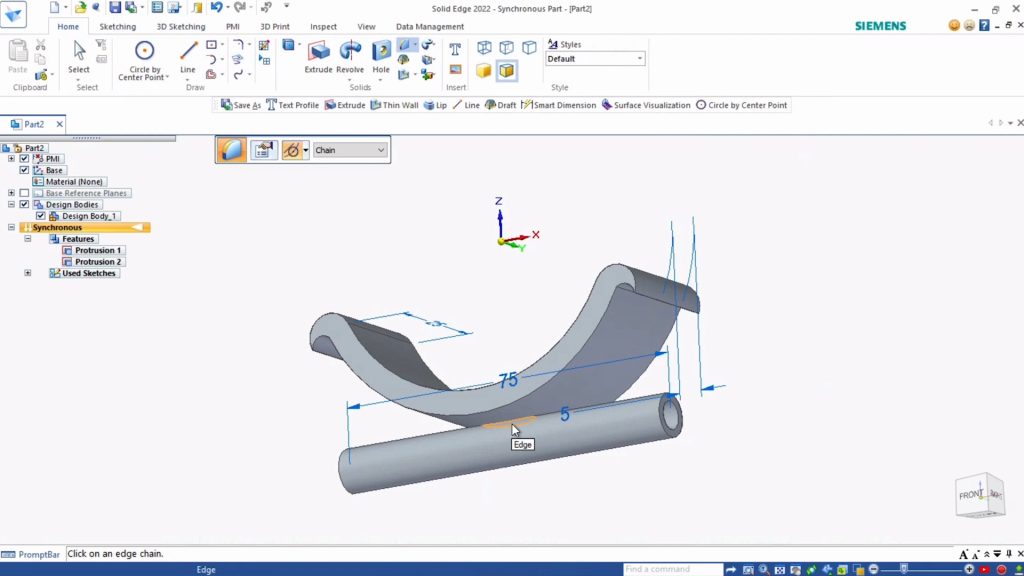
- Click on that area of connection and an option to enter a round amount will appear.
- Enter 2 mm.
- Hit Enter.
The tool forms rounded edges around both pieces at the same time, so that they fuse together, with one rounded edge around both.
Your chassis is complete! Remember you’ll need to print two of these—one for the front of your car, and one for the back. After printing your chassis, use the hooks and two rubber bands to strap them to your water bottle.
To make your car go, you’ll need to add axles and wheels.
Remember, you left a 6 mm hollow space in the axle holder for your axle to fit through. Try creating axles from different materials to see what works best: wooden skewers, coffee stirrers, stiff wire, thick pasta, or any other round and sturdy material. For our car, we use an axle of 100 mm (10 cm).
At either end of each axle, you’ll attach wheels. You can experiment here as well. Wheels can be made out of bottle caps or anything else round that will roll. Cut small holes in the center of your wheels and use hot glue to attach them easily.
How does changing the size and material of your wheels and axles affect your car’s performance? What makes it go fastest? What can carry the most weight? Can you add methods of propulsion so that your car moves on its own?
Challenge: To take this project to the next level, you can design your axle and wheels in Solid Edge and 3D print them. Here are the sizes we tried. Can you follow along?
- Axles: Using Circle by Center Point Tool, draw a 4 mm circle and extrude it to be 100 mm long. Print two of these and you have your axles.
- Wheels: In a second document, create a circle with a 40 mm diameter. Extrude the circle by 15 mm to create the base of a wheel. Next draw a second circle with a 4.25 mm diameter on the top of the cylinder you created, and extrude that down by 10 mm with the Subtract setting on. This creates a hole in the wheel to fit onto your axle. Finally, using the Round Tool, you can round the edges of the wheel. Print four of these and you’ll be ready to roll!
Okay!
Now You’re up!
- What else could this design (or the pieces of this design) become other than a car?
- What other types of objects could we make move using wheels?
- What other upcycled materials could we use, with the aid of 3D printed parts?
How did it go? Submit your feedback.